
This describes some antenna testing done by Ed Sim, N7RTA, Ryan Vandyke KF7RUQ, Jon Packer, KE7QOF and Charles Gray, KE6QZU. This test was conducted in the park north of the Daybreak Community Center, were we have our meetings on the third Thursday of each month at 7:00 PM. The testing was done on Thursday June 20, 2013. We started about 7:30 PM. The following equipment was used for the tests.
- Two Linksys wrt54g routers. These were version 2.o and version 2.2 routers with the mesh firmware version 0.4.3. (ke6qzu-m1 and ke6qzu-m2)
- Two 7 ah, 12 volt batteries.
- Standard 3.5 dBi omnidirectional antennas. This is the antenna that comes with the wrt54g routers
- 8 dBi omnidirectional antenna. HyperLink Model: HG2408U. 2400-2500 Mhz, 8dBi
- 12 dBi cube antenna. There is a special while supplies last. You will need to drill your own mounting holes. http://www.l-com.com/wireless-antenna-product-special-24-ghz-12-dbi-mast-mount-mini-panel-antenna-n-female-connector
- 16 dBi Yagi (1) antenna? Ed had modified the cable on the antenna and It did not perform well.
- 15 dBi omnidirectional antenna. http://www.ebay.com/itm/2-4GHz-15dBi-Omni-WiFi-antenna-RP-SMA-wireless-router-/171179228401?pt=US_Directional_Network_Antennas&hash=item27db13bcf1
- 16 dBi Yagi (2) antenna. This Yagi had a RP-SMA connector on the coax, so I had to use an adapter to connect it to the node.
Here is a link for a similar adapter. http://www.data-alliance.net/servlet/-strse-52/Adapter-RP-dsh-SMA-female-RP-dsh-TNC/Detail
Here is a link for a similar antenna on eBay. http://www.ebay.com/itm/16-dBi-High-Gain-Directional-Yagi-Outdoor-2-4GHz-Wireless-Wi-Fi-Antenna-/350931822288?pt=US_Directional_Network_Antennas&hash=item51b52aa6d0 - Two folding tables to hold the batteries, computer and router, etc.
- Two tripods. One for each table.
- Tube clamps to hold the antennas to the tripods.
http://www.allelectronics.com/make-a-store/item/CLMP-3/WALL-MOUNTABLE-TUBE-CLAMP-USED/1.html - Laptop Computer to gather data from the router at station #1.
The pictures that I took during the test were lost. (Hard disk crash on my laptop) I do have some pictures that were taken by Ed (N7RTA). I also have similar pictures from a later test that I will use.
We set up a mesh node on each of the tables powered by a battery. We started with the standard 3.5 dBi antennas on each router. Each router was configured to use the right antenna. We wanted to see how each antenna performed, and what kind of distance we can get. The first set of data we collected at each location was with the standard antenna. This was to be a reference that we could use to compare the difference in readings when the antenna on the node at location #2 and later location #3 was changed to one of the other antennas. We first made sure that the routers were working with the tables located next to each other. Then one of the tables was moved to until the signal disappeared from location #1. We then moved the table closer so we could connect. This was called location #2. After gathering data for all the antennas from location #2 the node was moved to location #3 and we repeated the process. (Well almost) All the readings were taken from the node at location #1. The GPS readings for the locations are as follows:
Here is a view of the test site.

#1) 40° 32’25.98” N, 111 ° 59’ 54.9” W
#2) 40° 32’ 25.98” N, 111° 59’ 57.48” W
#3) 40°32′ 26.196″ N, 112° 3′ 40.32″ W
Location #1 to location #2 distance is 201 ft. The free space loss is: 75.8 dB at 2.4 GHz

Location #1 to location #3 distance is 748 ft. The free space loss is: 87.2 dB at 2.4 GHz

We learned a lot from this experience. We discovered that we would like readings from both of the nodes used in the test. We also needed two computers to gather the data. We found that when we powered off the node at station #2 and changed the antenna we sometimes also had to reboot the router at station #1 to get readings. this also occurred when the node at location #2 was moved to location #3. We also discovered that the wind could remove the laptops from the tables. (The laptops slide on the table tops very well and the display worked well as a sail.)
Here is a picture of a table set up at location #1 from a later test.

Here is a picture of the tripod used at location #2 and #3

Here is a picture of the tripod used at location #1

Here is a picture of the 8 dBi antenna
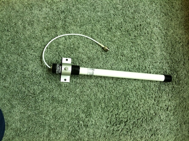
Here is a picture of the 12 dBi Cube.

Here is a picture of the 16 dBi Yagi

Here is a picture of the 15 dBi omnidirectional antenna

Here is the data that we collected
|
Test # |
Site # |
Antenna |
Site # |
Antenna |
Signal dB |
*Gain |
Noise dB |
Signal/Noise dB |
|
|
1 |
1 |
3.5 dBi |
2 |
3.5 dBi |
-95 |
0 |
-88 |
-6 |
|
|
2 |
1 |
3.5 dBi |
2 |
8 dBi |
-81 |
7 |
-88 |
7 |
|
|
3 |
1 |
3.5 dBi |
2 |
16 dBi Yagi (1) |
-89** |
6 |
-88 |
-1 |
|
|
4 |
1 |
3.5 dBi |
2 |
16 dBi Yagi (1) |
NA |
NA |
NA |
NA |
|
|
5 |
1 |
3.5 dBi |
2 |
12 dBi Cube |
-60 |
35 |
-87 |
27 |
|
|
6 |
1 |
15 dBi |
2 |
3.5 dBi |
-71 |
24 |
-85 |
14 |
|
|
7 |
1 |
3.5 dBi |
3 |
3.5 dBi |
NA |
NA |
NA |
NA |
|
|
8 |
1 |
3.5 dBi |
3 |
8 dBi |
-76 |
NA |
-87 |
11 |
|
|
9 |
1 |
3.5 dBi |
3 |
16 dBi Yagi (1) |
-87** |
NA |
-88 |
0 |
|
|
10 |
1 |
3.5 dBi |
3 |
12 dBi Cube |
-71 |
NA |
-88 |
17 |
|
|
11 |
1 |
3.5 dBi |
3 |
16 dBi Yagi (2) |
-75 |
NA |
-90 |
16 |
|
|
12 |
1 |
3.5 dBi |
3 |
15 dBi |
NA |
NA |
NA |
NA |
|
|
13 |
1 |
16 dBi Yagi (2) |
3 |
12 dBi Cube |
-51 |
NA |
-89 |
38 |
|
|
14 |
1 |
15 dBi |
3 |
12 dBi Cube |
-63 |
-88 |
25 |
||
|
15 |
1 |
15 dBi |
3 |
8 dBi |
-71 |
-88 |
16 |
||
|
16 |
1 |
15 dBi |
3 |
3.5 dBi |
NA |
NA |
NA |
NA |
|
|
17 |
1 |
16 dBi Yagi (2) |
3 |
3.5 dBi |
-75 |
NA |
-90 |
16 |
|
Test #1 is the reference. The signal level shown is the minimum level (for this router) to maintain a link.
* gain as represented here is not dBi, rather it is with respect to the standard antenna shown and is estimated based on signal strength.
** this data represents an anomaly! Based on spacing you would expect ~11dB difference.
Data shown in test #11 was not measured, it is based on reciprocity with test #17